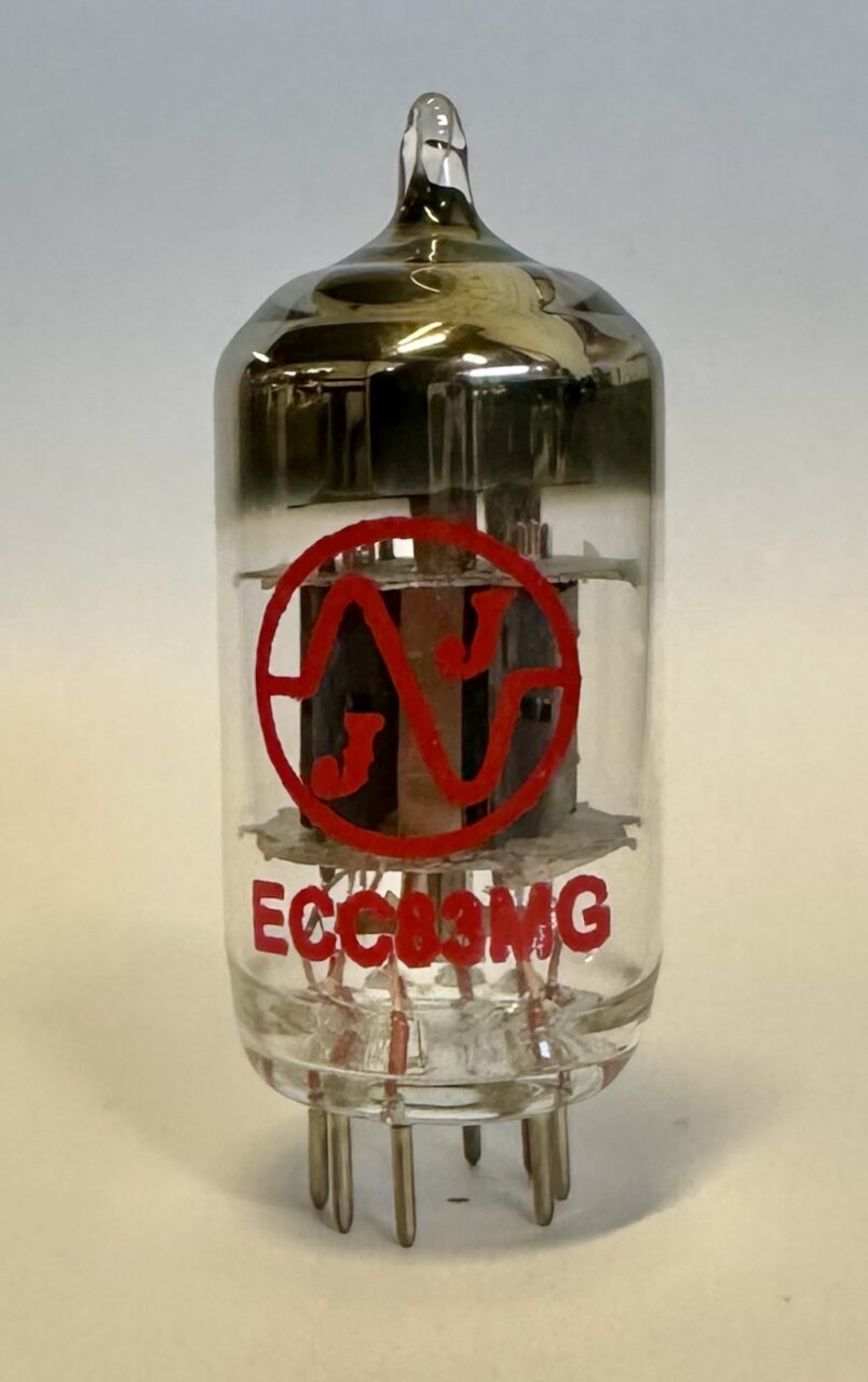
Introduction: The JJ ECC83MG has been in continuous production since late 2013. This tube was envisaged to represent a mid point between the classic short-plate JJ ECC83S and long-plate JJ ECC803S.
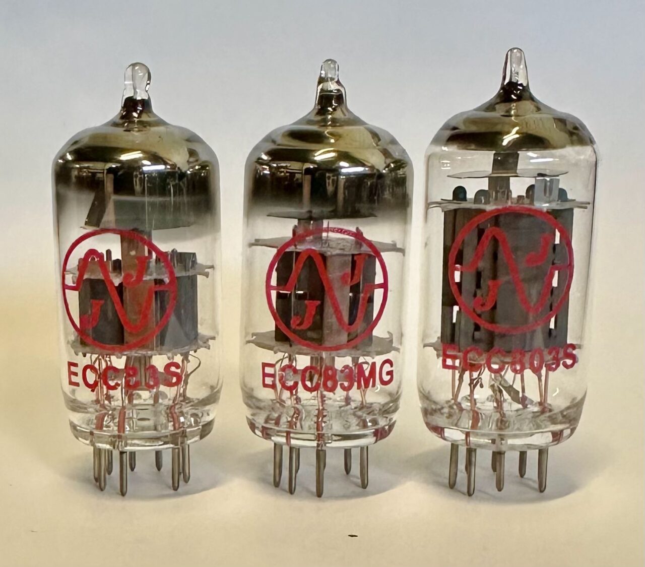
In many ways the MG is the most classic or traditional 12AX7 type in JJ’s catalog. The plate length and inner-electrode geometry are similar to many of the medium plate length 12AX7/ECC83’s from historic manufacturers such as RCA, GE, Raytheon, Mullard, Amperex, etc. These tubes are known for having a very even-handed overall sound, with a smooth character. The guitar players appreciate their warm overdriven tone with a nice sweet spot as the tube transitions from clean to clipping. Audio lovers enjoy the versatile and balanced overall sound.
In comparison these classic midland 12AX7’s will not have the upper mid bump and high-end presence that you would expect from a long plate 12AX7, like the classic Telefunken ECC83, JJ ECC803S, or Sovtek LPS.
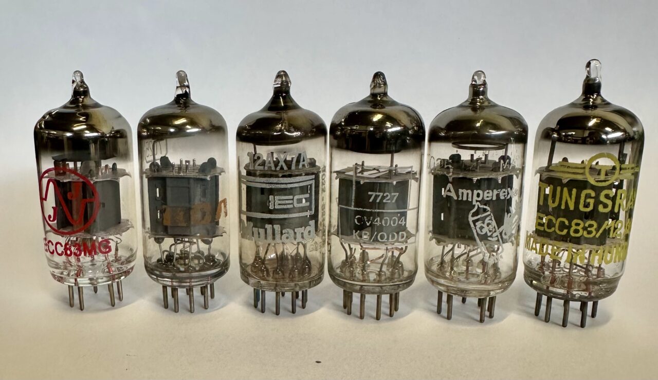
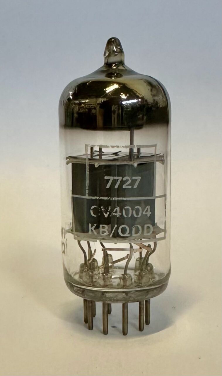
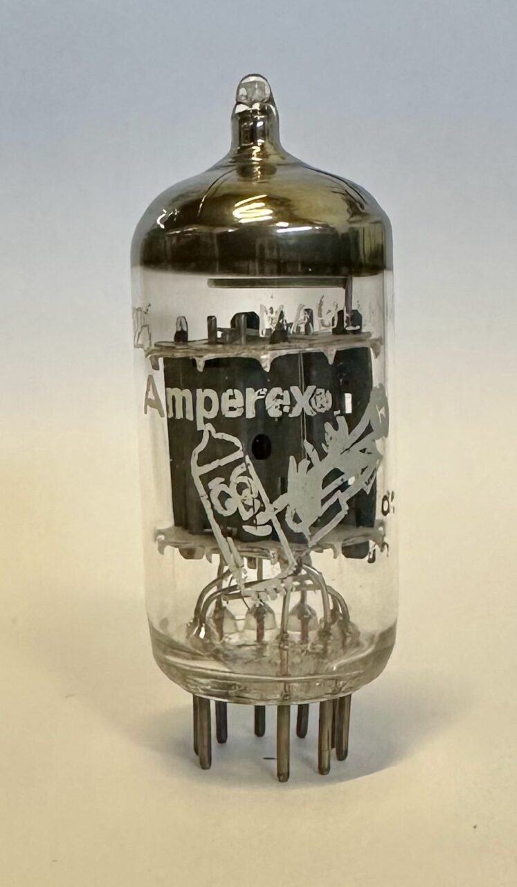
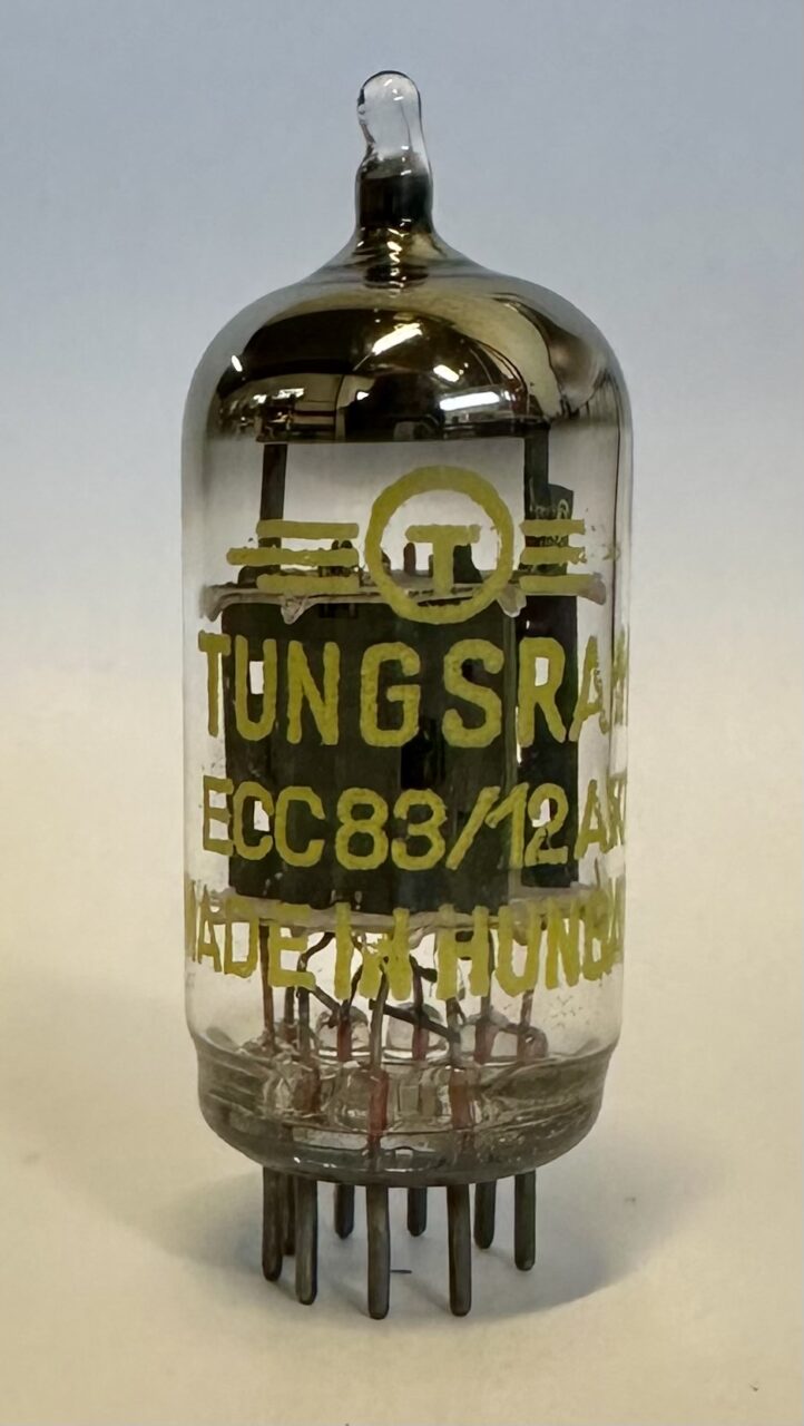
Semantics aside, let’s continue our journey toward the center of the of the medium plate length 12AX7 genre. To kick things off we devised a simple test setup to evaluate and compare the open loop gain and distortion characteristics, under both loaded and ideal operating conditions. To represent the medium plate length 12AX7 family we selected some of favorite classic 12AX7/ECC83 types, to test alongside the MG. This will include the ubiquitous “short-ish” grey plate RCA 12AX7A/7025, a 60’s era Black Burn produced Mullard ECC83, the heralded Mullard CV4004, a Dutch built Amperex “Bugle Boy” 7025, and the Hungarian made Tungsram ECC83.
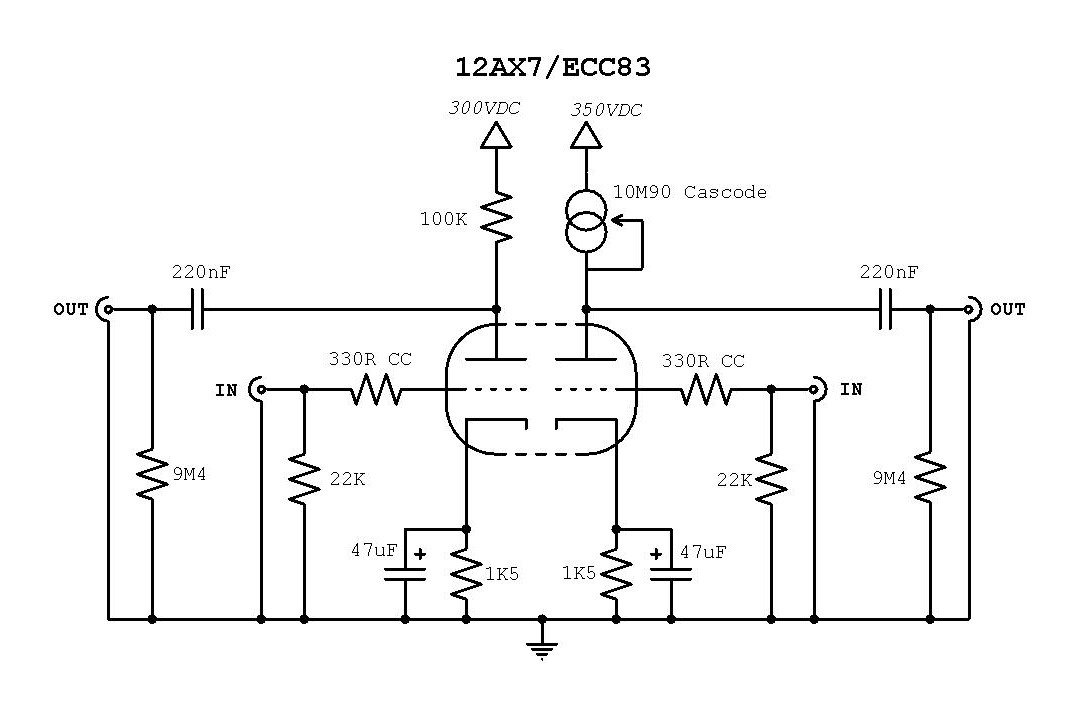
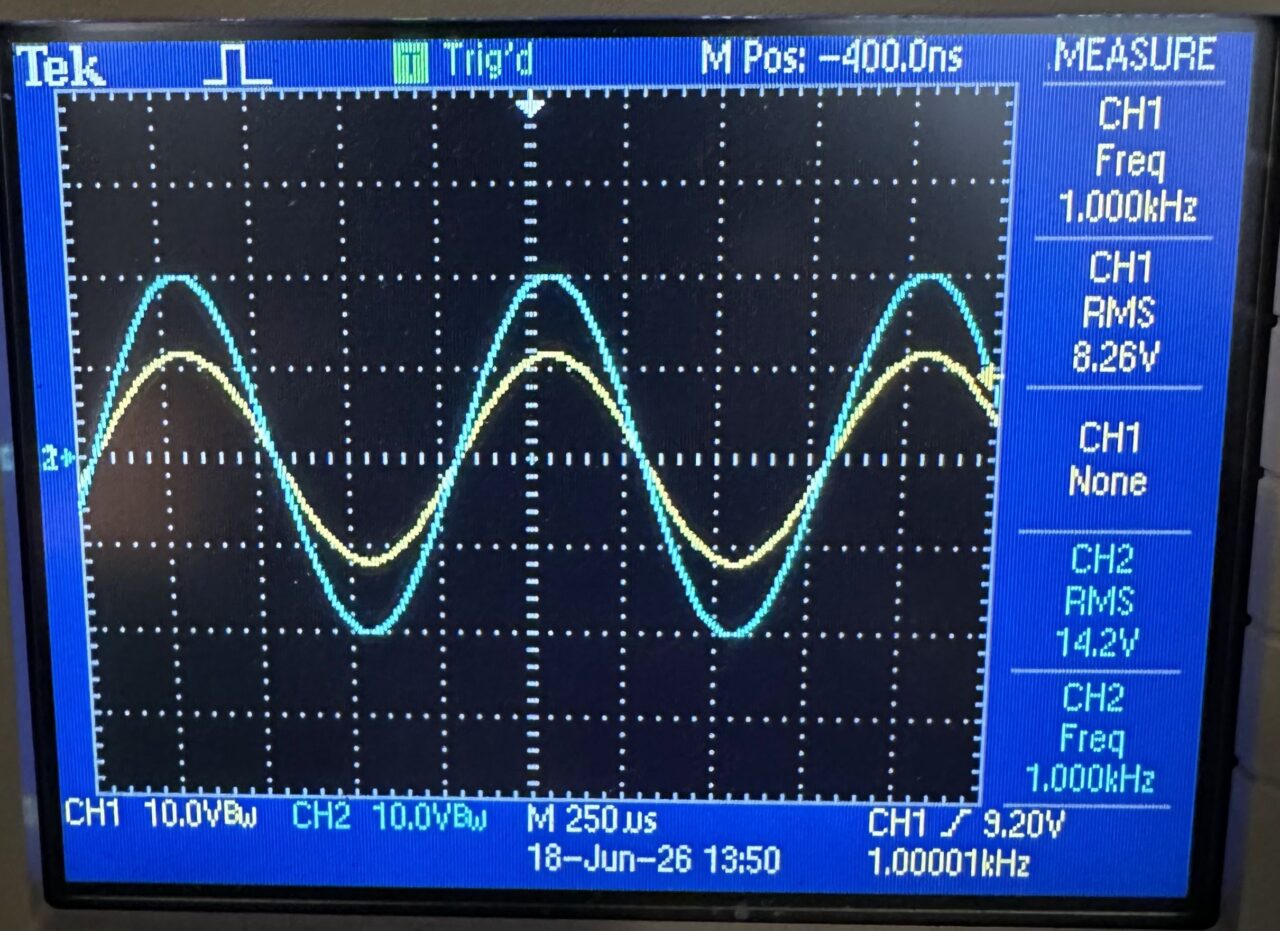
The first test utilizes the 12AX7 in the common-cathode amplifying topology, with a 100K plate load, 1K5Ω cathode bias resistor, and a 47uF cathode bypass cap. This circuit can be found in many classic guitar amplifiers and audio applications. In our case the B+ is 300VDC, provided by an actively regulated low impedance bench supply. In this configuration the 100K plate resistor loads down the 12AX7 considerably, as it’s less than 2x the tubes internal plate impedance. This brings the gain down from the data sheet bogey value of 100, to around 60. This also drives up the tube’s “intrinsic” distortion.
The second test is the same common-cathode voltage amplifier but utilizing an active current source as the plate load. The 1K5Ω/47uF cathode bias arrangement is retained. The constant current source is a cascode pair of IXYS 10M90’s, which puts the effective resistance in the 5-6MΩ range, at our 1KHz test frequency. The use of an extremely high effective plate impedance load allows us to measure both the actual gain and “unloaded” distortion characteristics. Here’s a simplified schematic of the test setup:
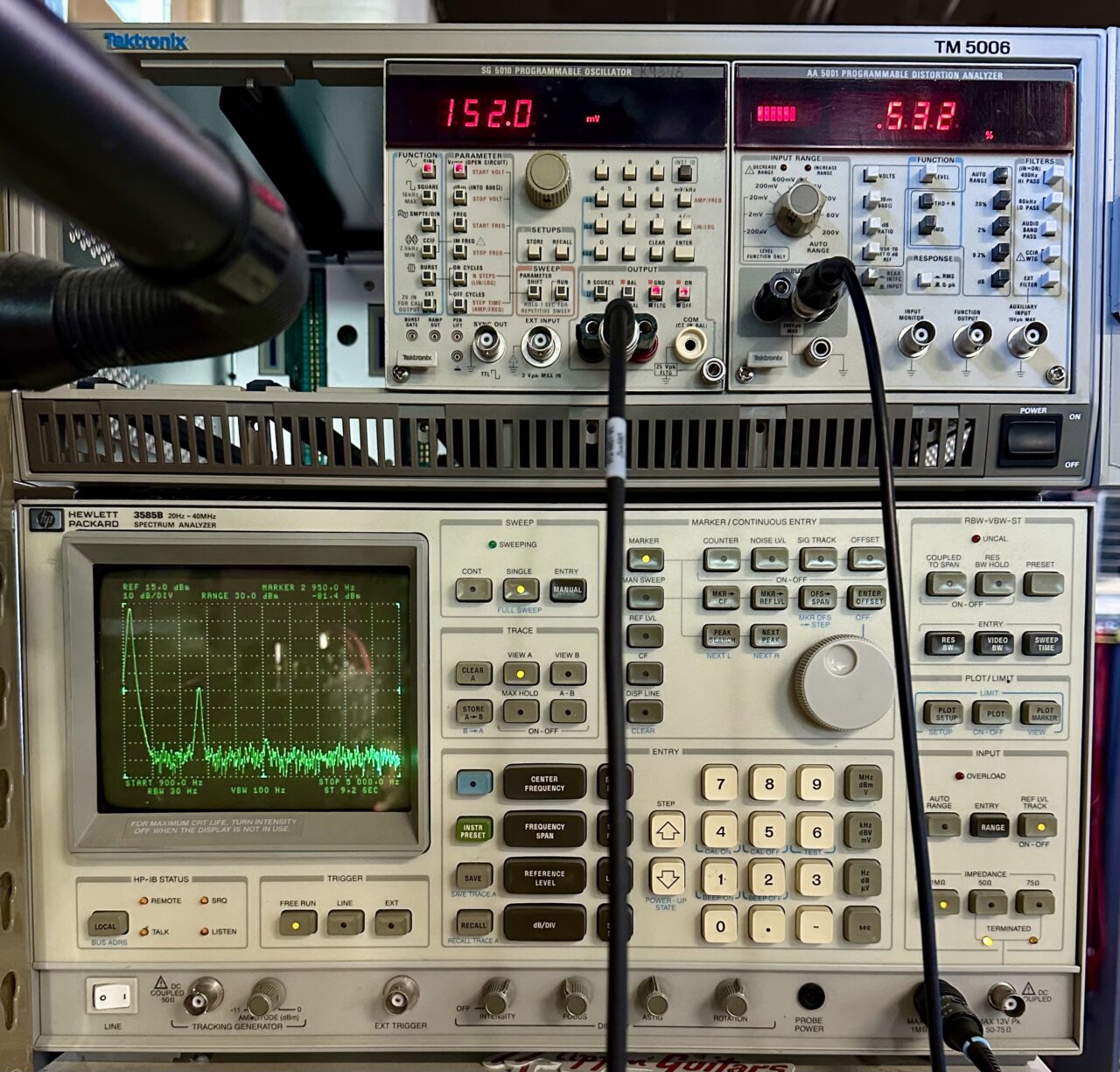
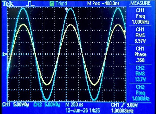
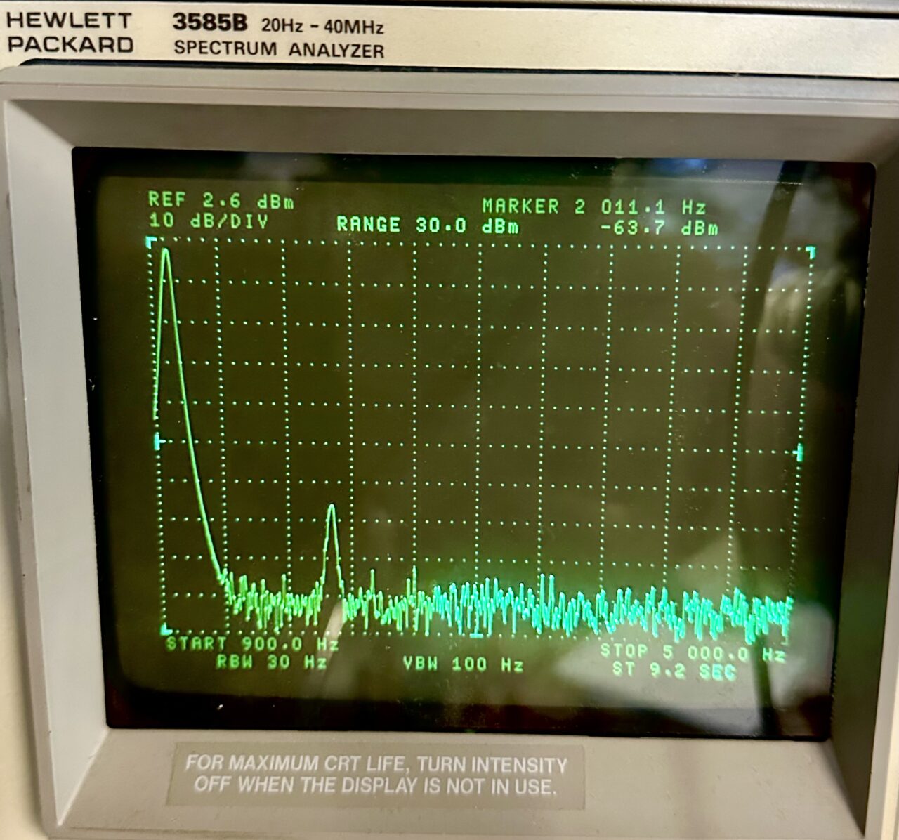
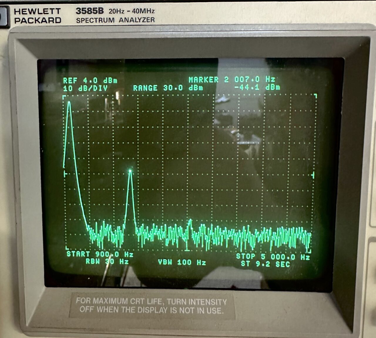
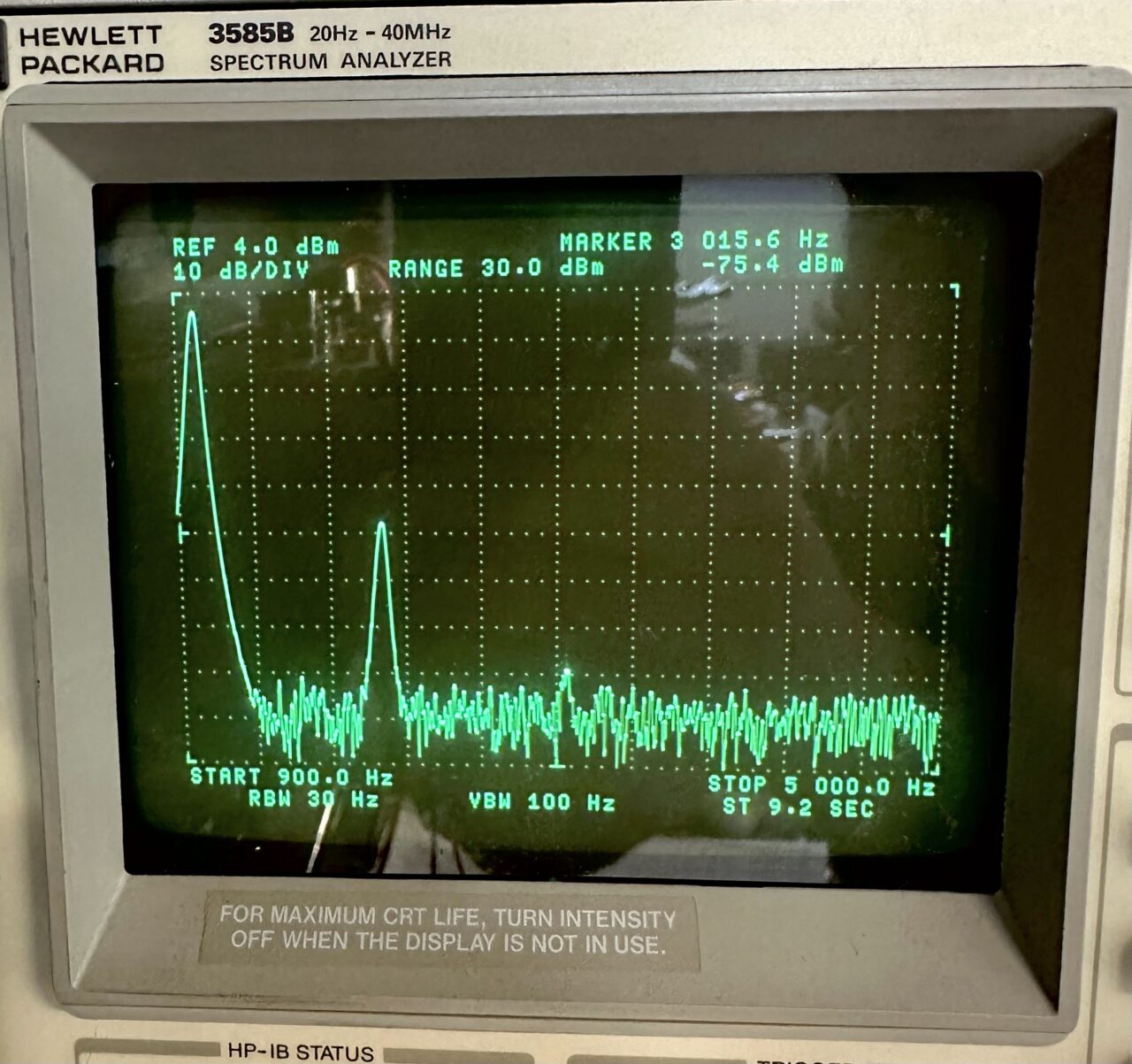
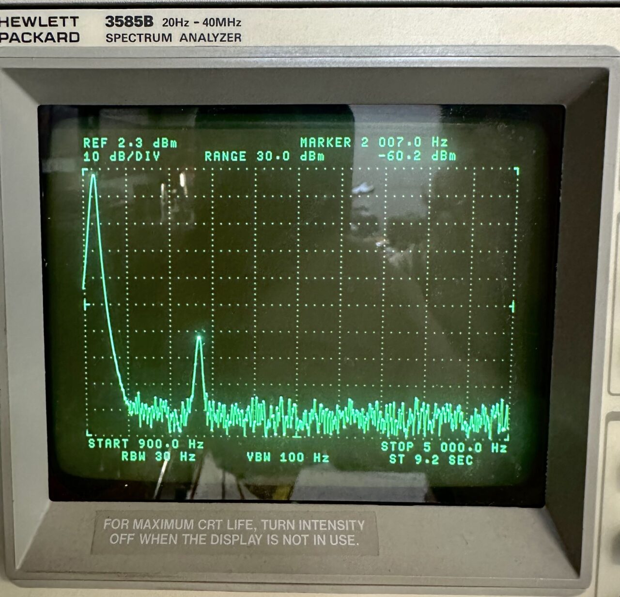
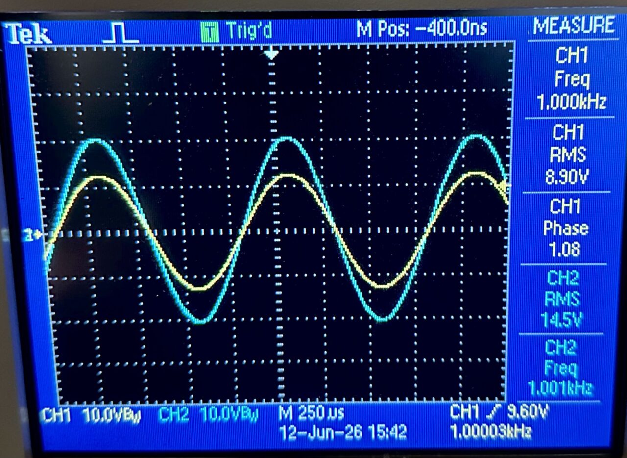
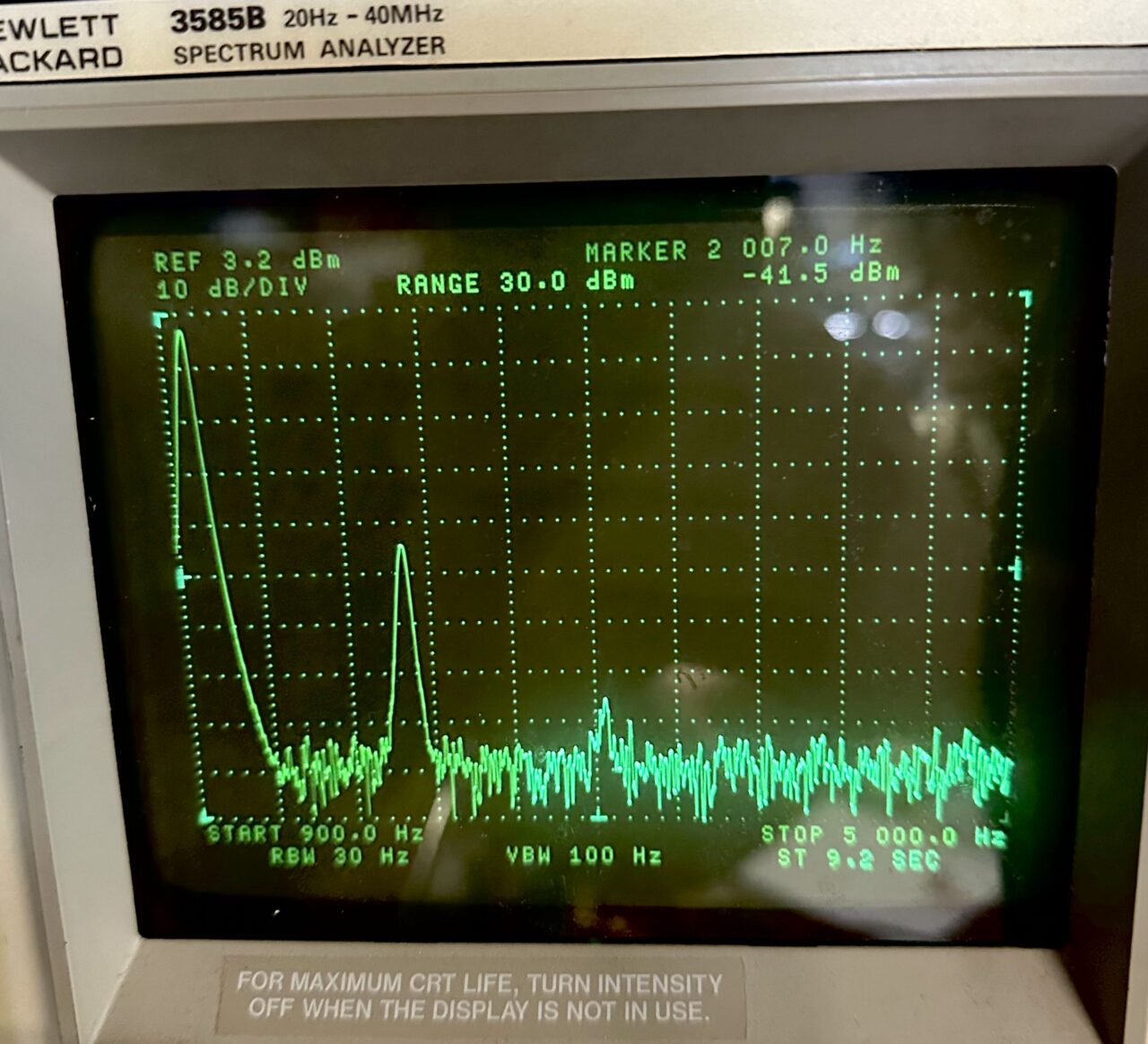
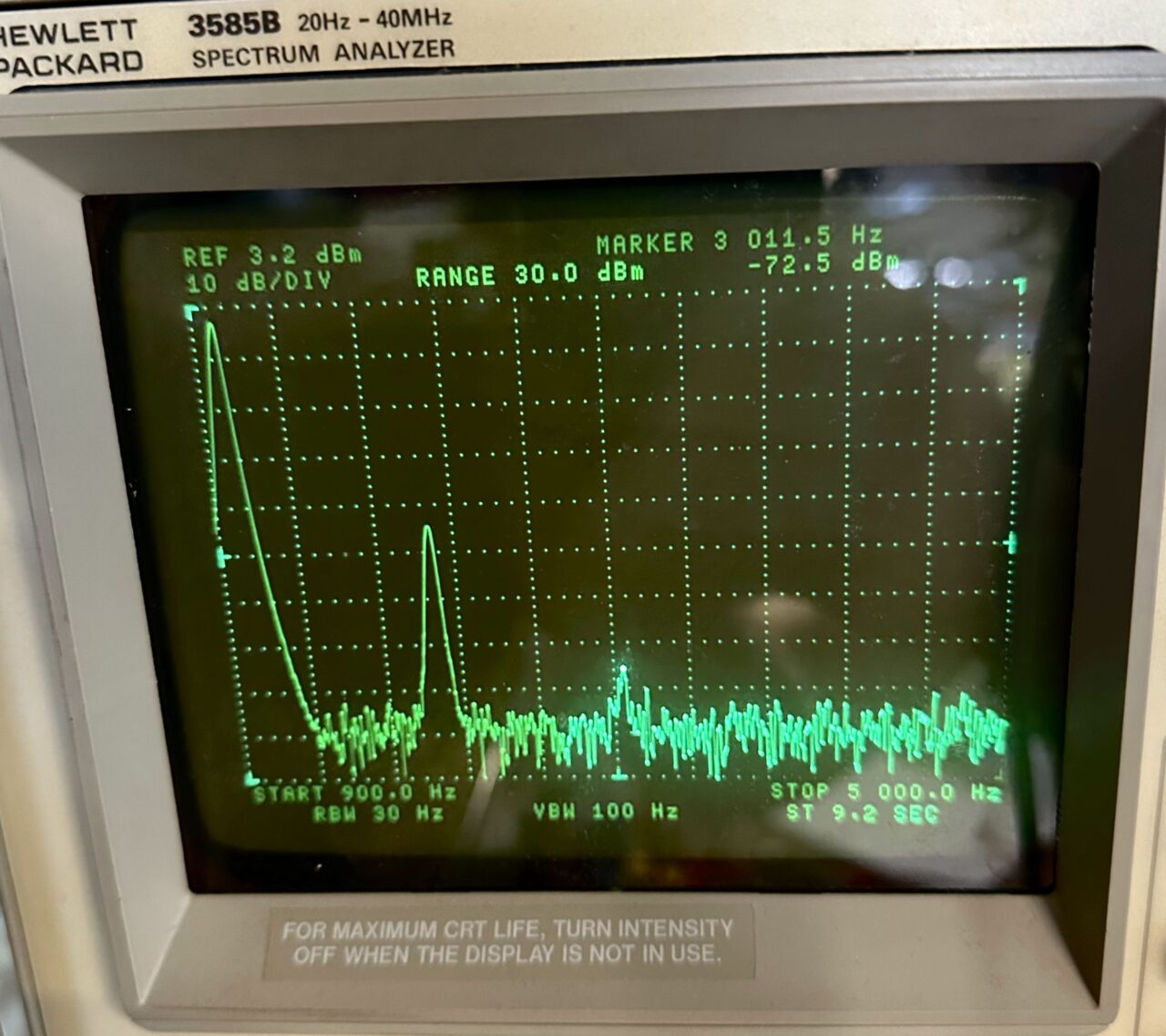
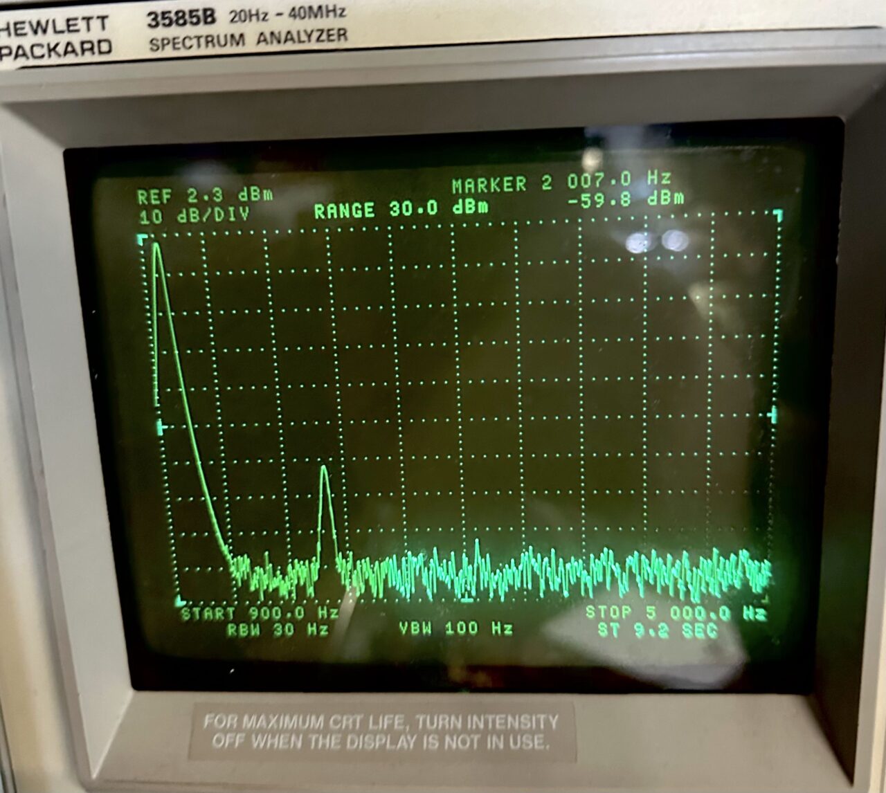
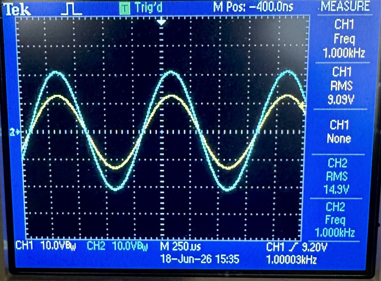
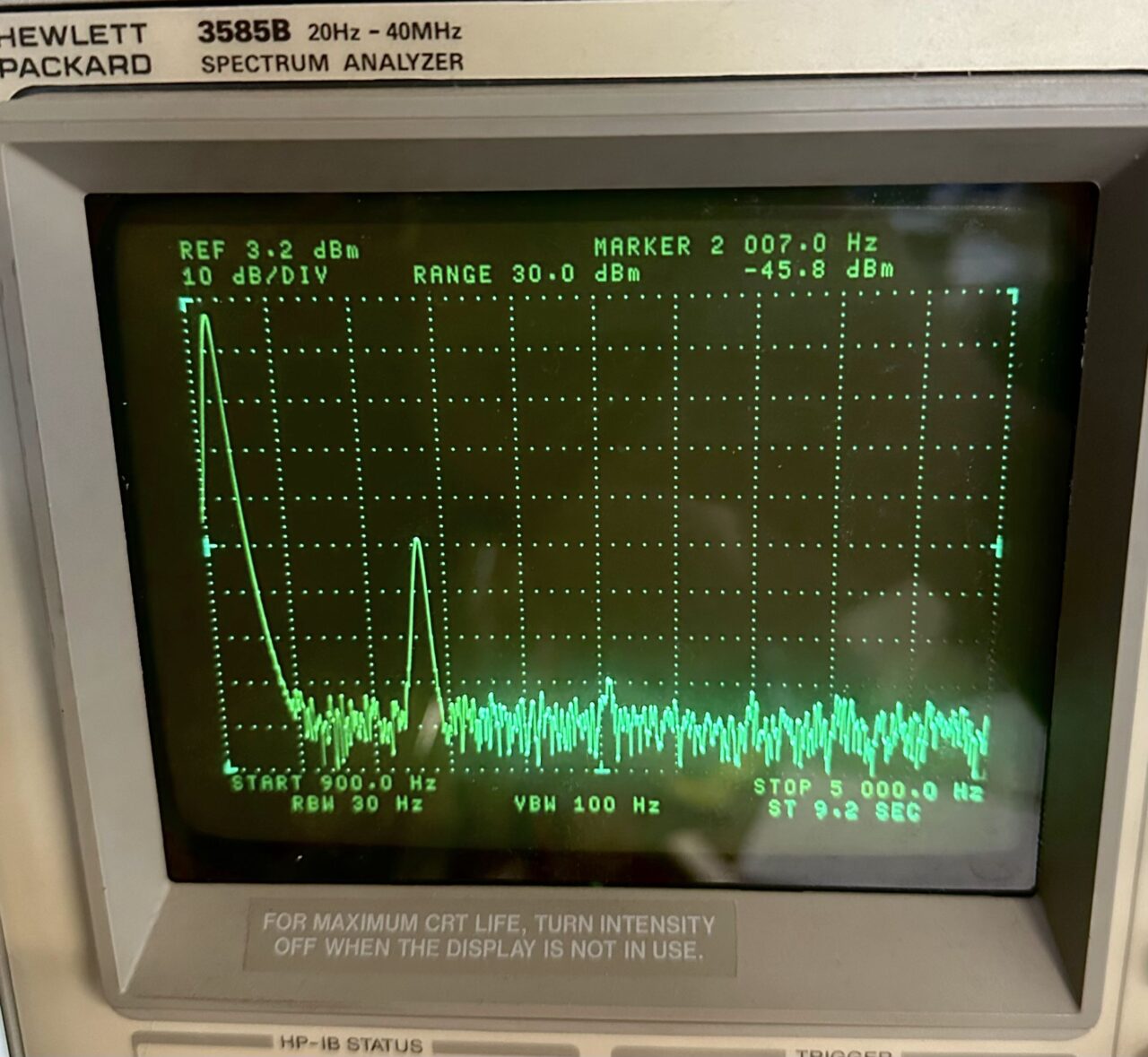
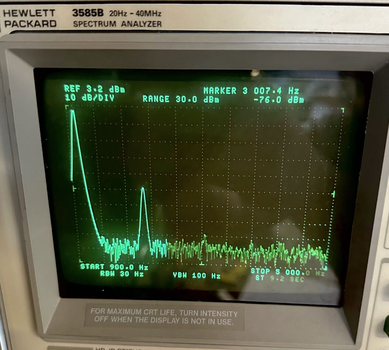
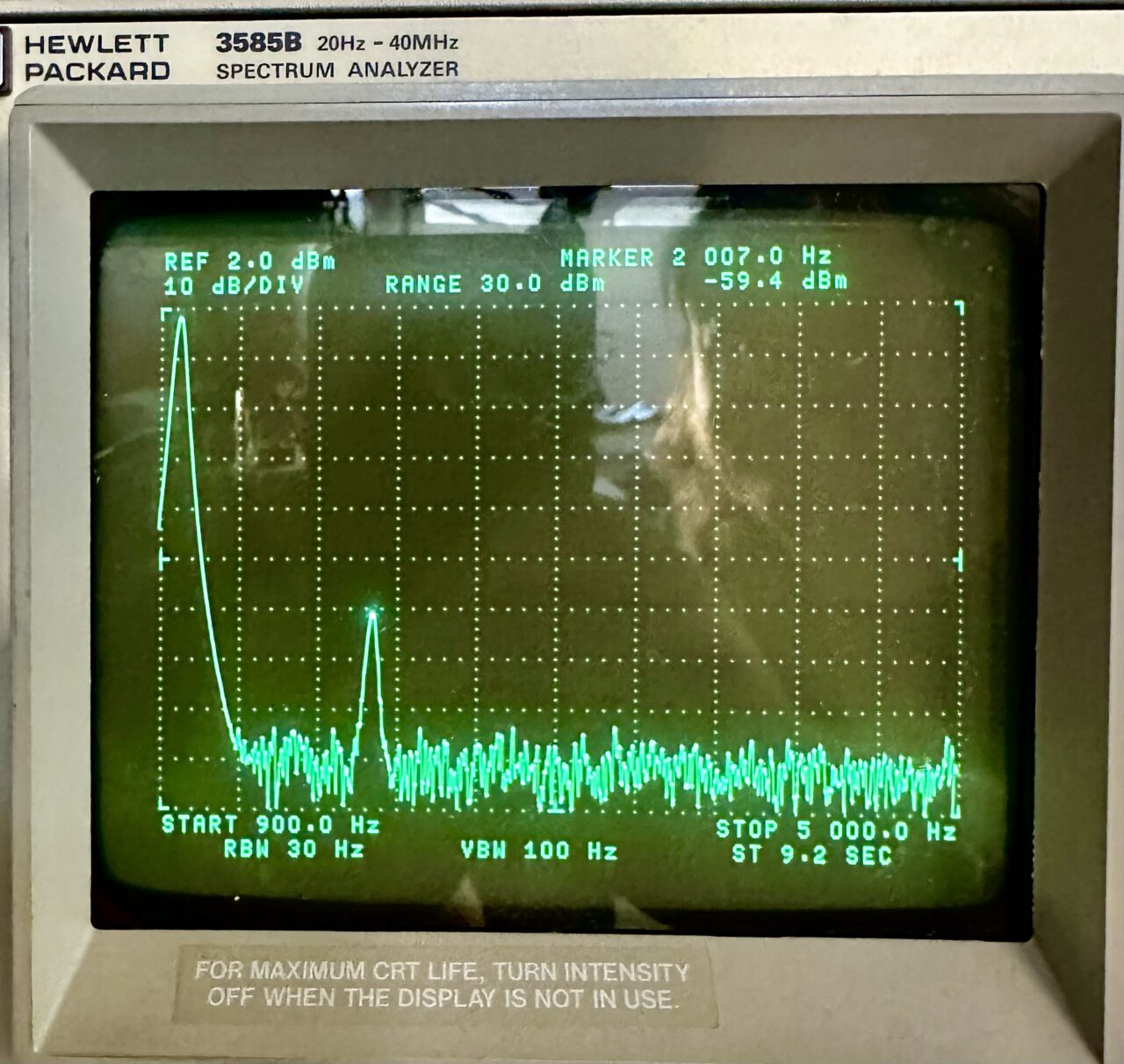
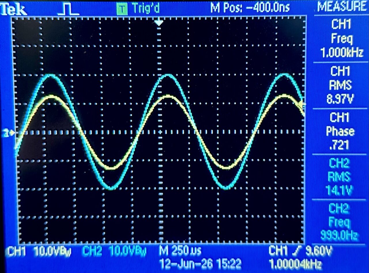
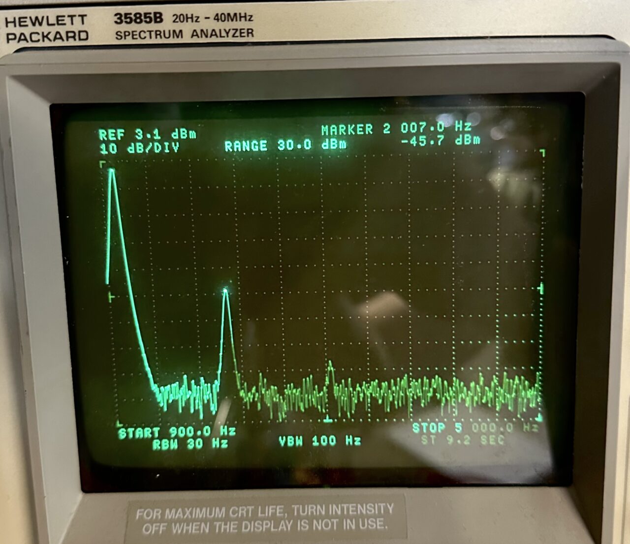
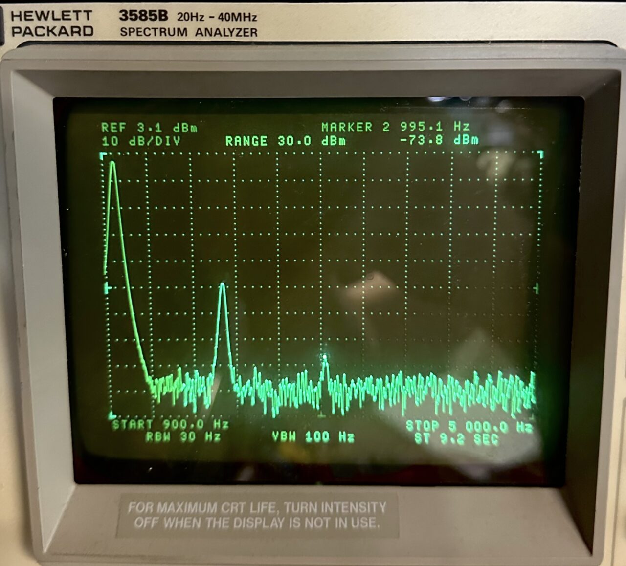
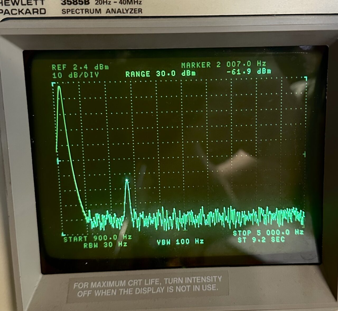
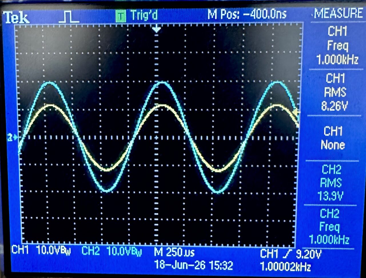
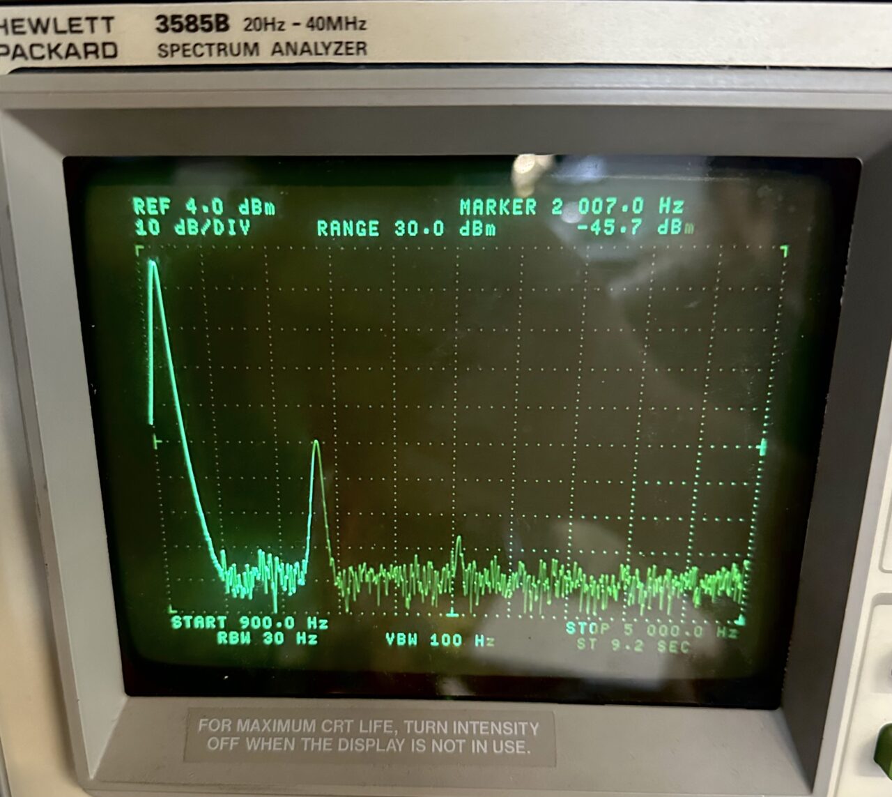
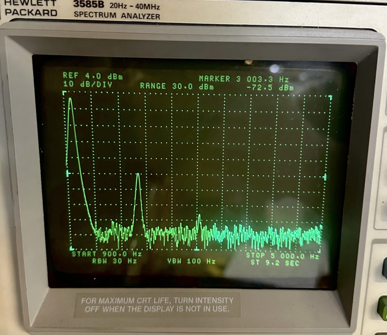
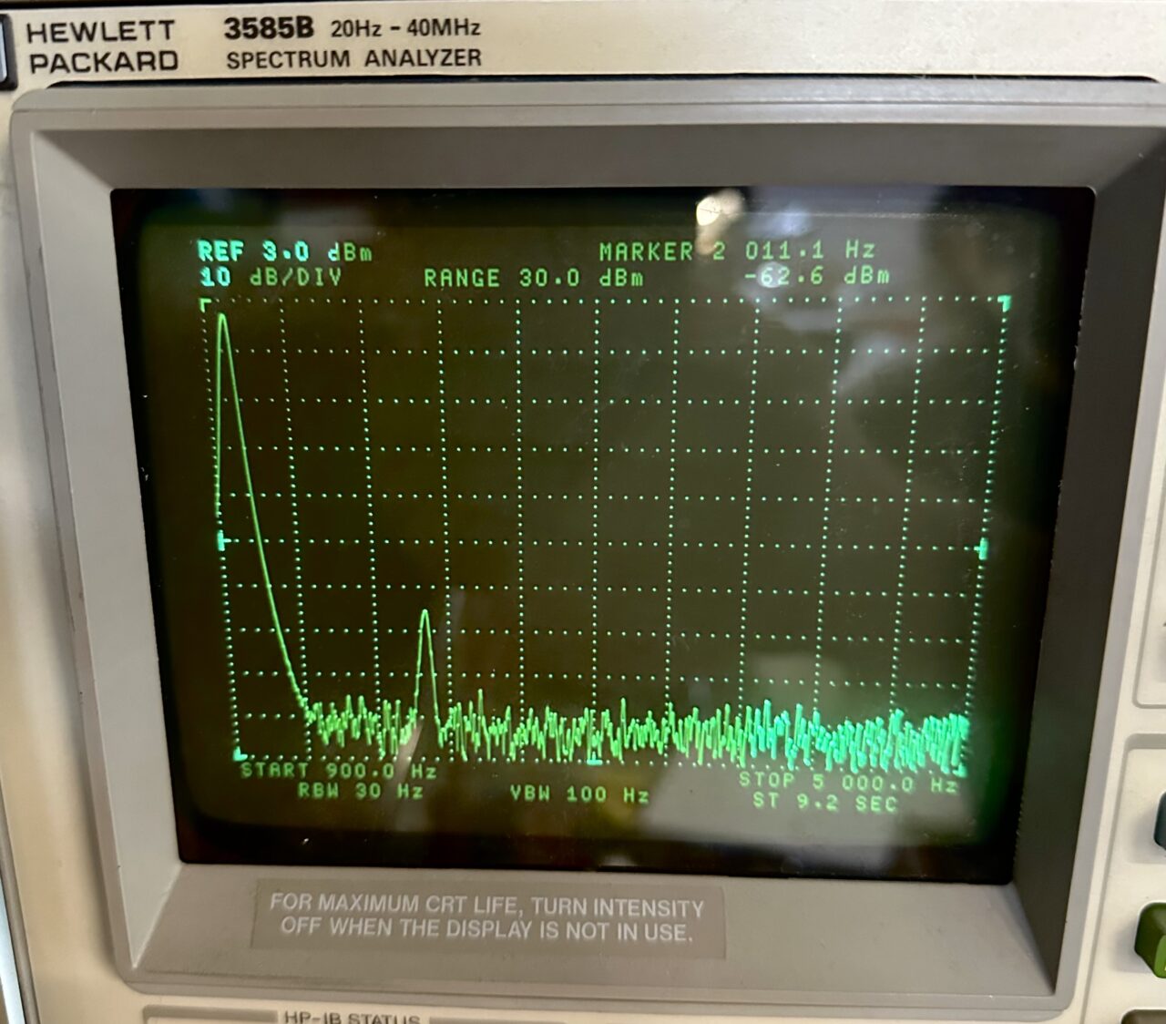
For test gear we’re going old school with the classic Tektronix AA5001 distortion analyzer and the companion SG5010 signal generator, along with an HP3585B spectrum analyzer. The inputs on both the AA5001 and 3585B have been optimized to minimize any additional loading. For the gain test we’ll use our Tek TDS2012. The test signal is 150mVRMS at 1KHz. All the tubes were tested to insure all parameters were +/-15% of the classic 250V, -2Vg1, 1.2mA characteristics.
Test Results
For each tube we will record the DC operating points, Plate Voltage Vp, Cathode bias voltage Vk, and the measured in circuit gain (µ). Keep in mind the 100K µ is the “loaded” gain, which represents the actual real world gain you would find in a typical 12AX7 gain stage. Whereas the CCS µ is ideal, and can be compared directly to the book spec bogey value of 100x. For the distortion analysis we’re looking at the 2nd harmonic H2, the 3rd harmonic H3, and total harmonic distortion THD. Lastly we will note the tubes Contact Potential for each triode. Contact potential is a relative but useful measure of the “cathode to control-grid” relationship. In it’s most basic form this represents the bias point at which the grid “turns-on” and starts to conduct current, which becomes a critical factor when dealing with low current tubes such as the 12AX7. All things being equal a lower contact potential represents a more ideal compromise in terms of materials, coatings, space-charge, and geometry. Though it must be considered with all other measured characteristics.


Test Results Summary
Here we can see good overall performance with all of these medium plate length 12AX7 types. The JJ ECC83 MG and Mullard CV4004 had the highest loaded gain performance at 60x and 61x respectively. Looking closer at these two tubes the CV4004 had an unloaded gain of 99x, which was the highest measured in the group, while the MG clocked in at 91.3x which is the lowest of the group. The discrepancy arises due to differences in transconductance and internal plate impedance. So while the MG has slightly less unloaded gain, in most real world applications the in-circuit gain will still be quite high due to it’s slightly lower than average plate impedance, and higher than average transconductance.
Here are the tubes ranked in order of the measured gain with the 100K load:

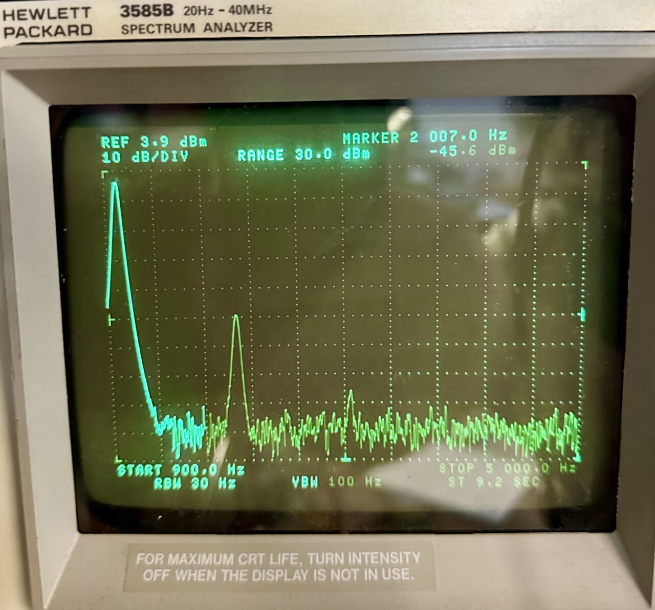
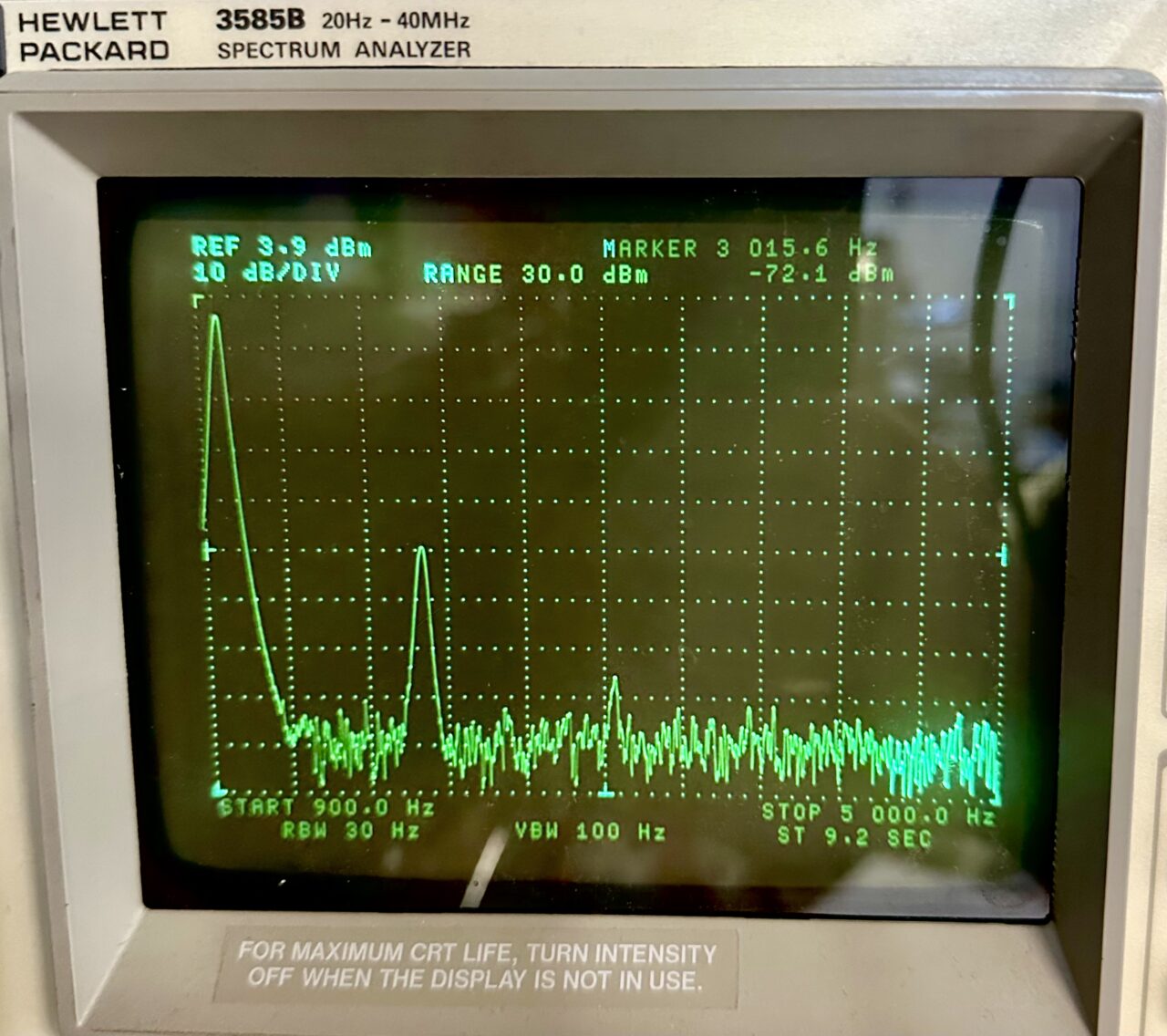
In terms of distortion the JJ ECC83 MG had the lowest measured THD in the CCS circuit at 0.13%. While the Mullard 12AX7A had the highest distortion, in both the 100K and CCS loaded configurations (0.8% and 0.17%). In general it has been observed that distortion characteristics can easily vary by 2:1 or more, from tube-to-tube within a give tube type category (medium plate length 12AX7’s for example). However in this case we see a tighter than average distribution for all characteristics.
Here are the tubes ranked in order of the measured THD with the 100K load:

Regarding contact potential, the voltages recorded here represent the onset of grid conduction. Like any diode, this could be curve traced to further characterize the turn-on and “knee” of the grid-to-cathode (junction) relationship. This would provide some unique insights, particularly in regards to clipping and end-of-life characteristics. However, I think we’ll save this for a dedicated article 🙂
Deconstruction
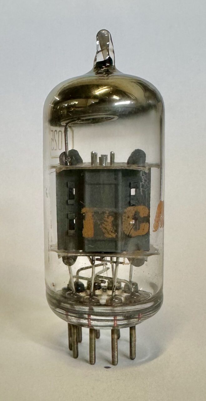
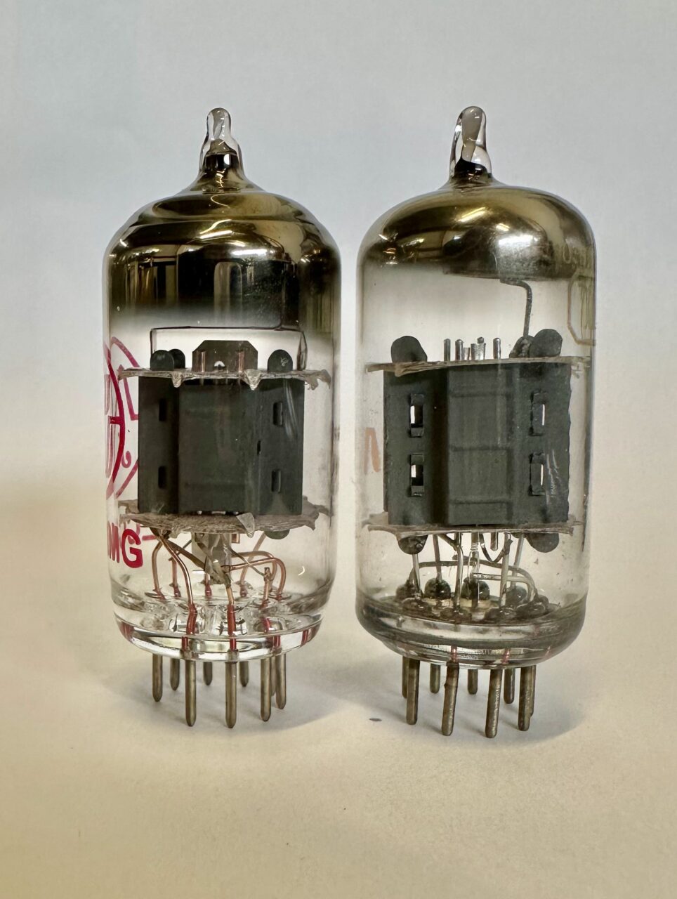
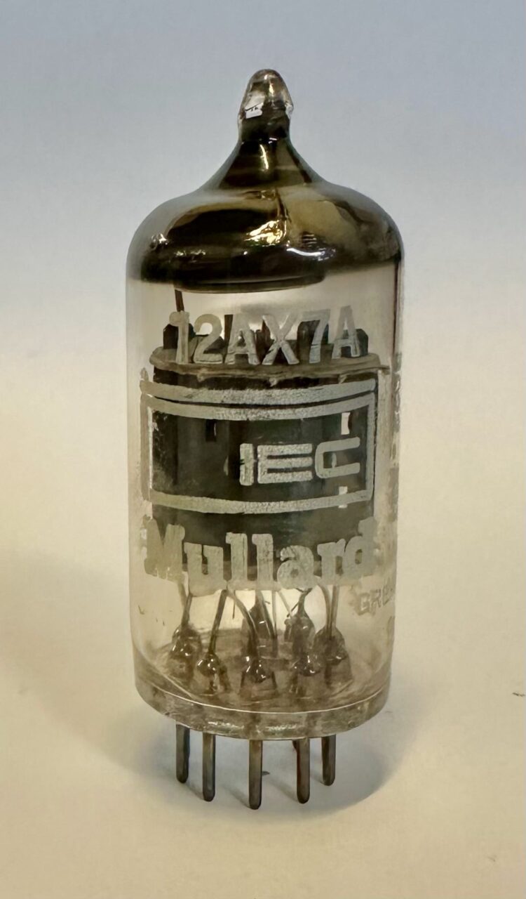
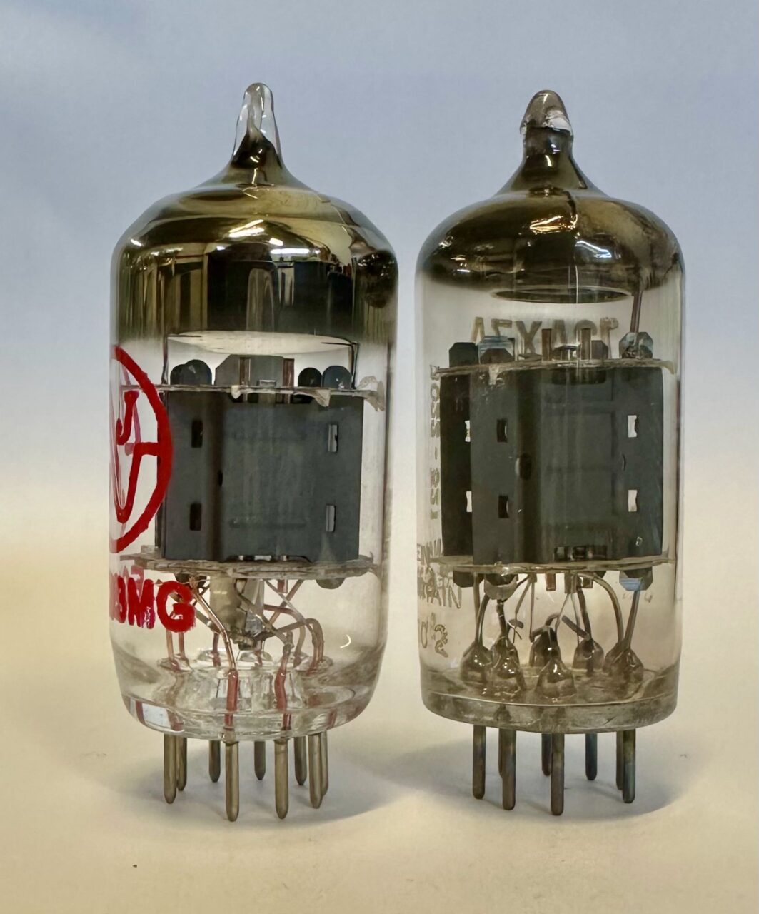
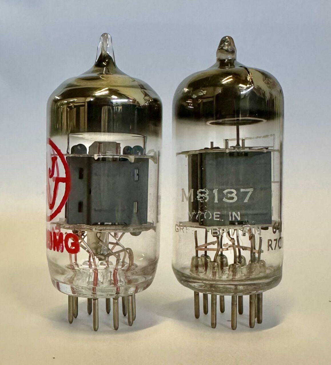
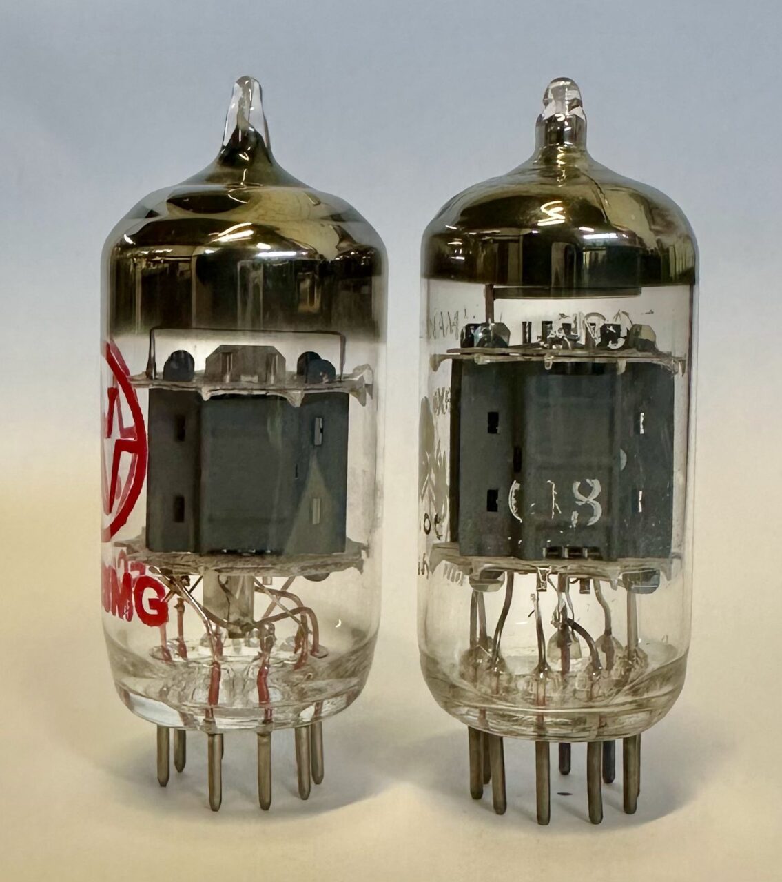
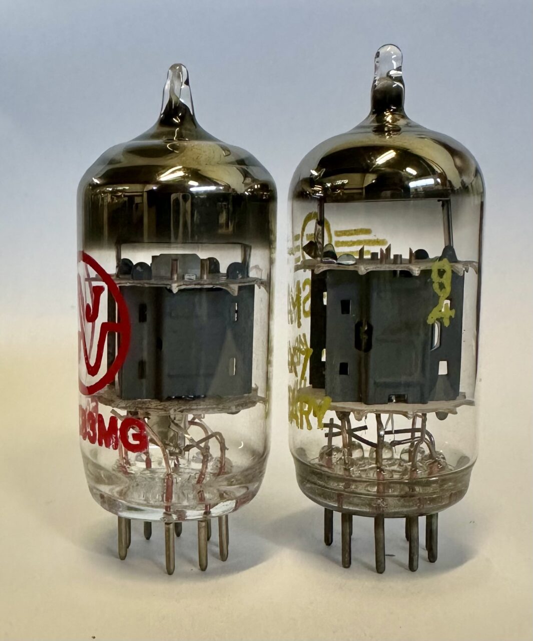
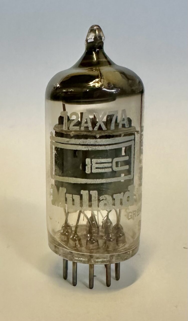
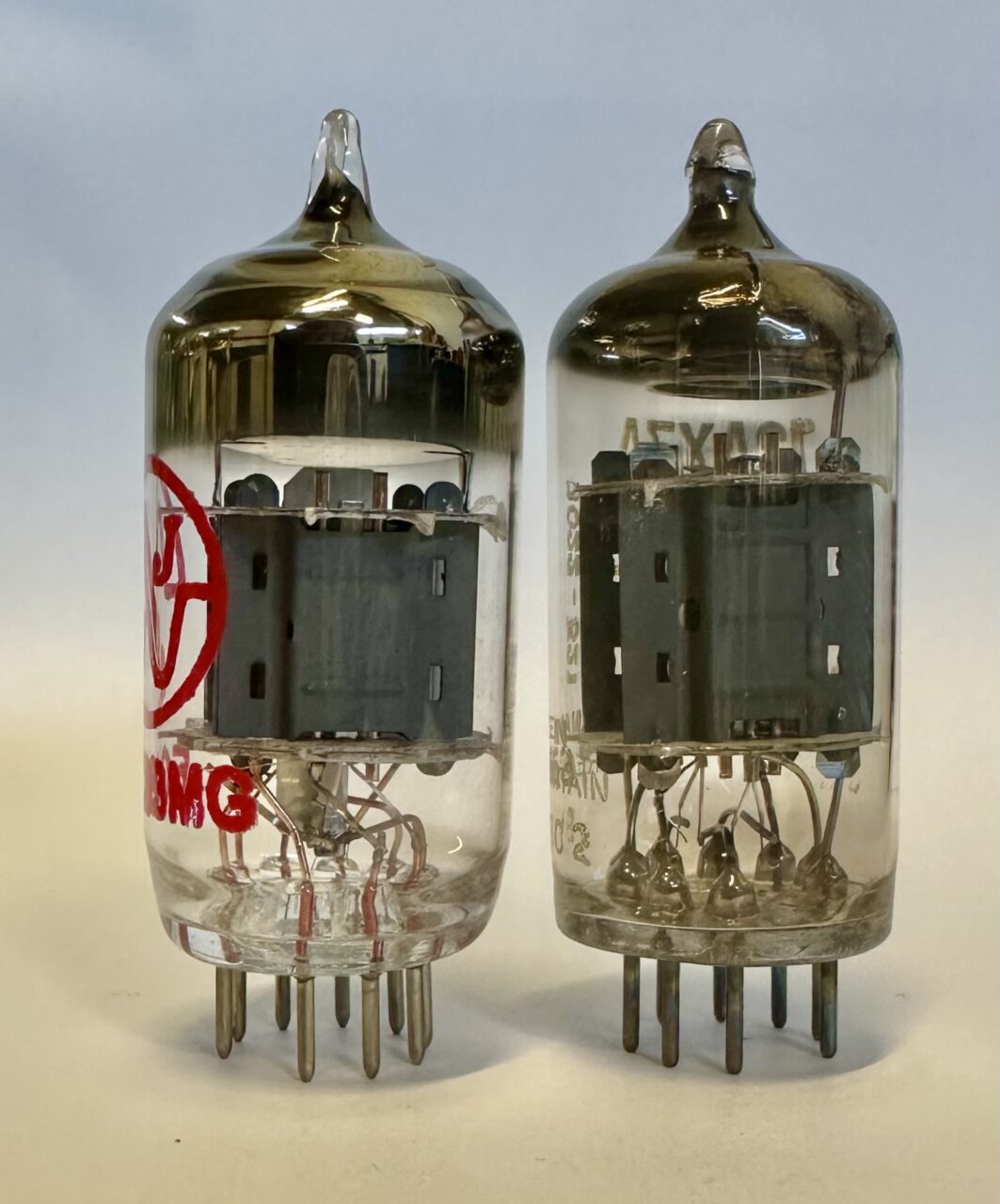
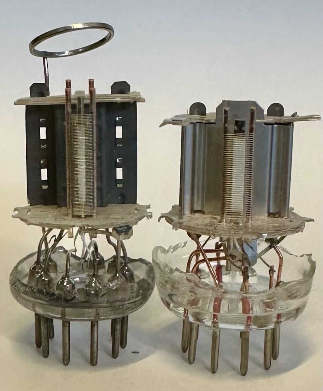
Let’s look at the internal components that makeup the JJ ECC83 MG. We’ll also compare side-by-side with a vintage/original 60’s Blackburn Mullard produced 12AX7 (don’t worry, it had a dead section…).
To start we can see that the overall physical dimensions of the envelope and pins are very similar, with the OD on the MG being just slightly larger at 0.840″, whereas the Mullard comes in at 0.800″ exactly. In the side-by-side pic we can see the plate length on the Mullard is slightly longer, more on this to come:
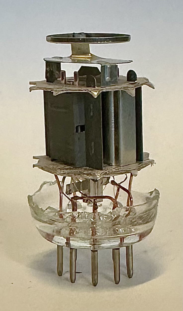
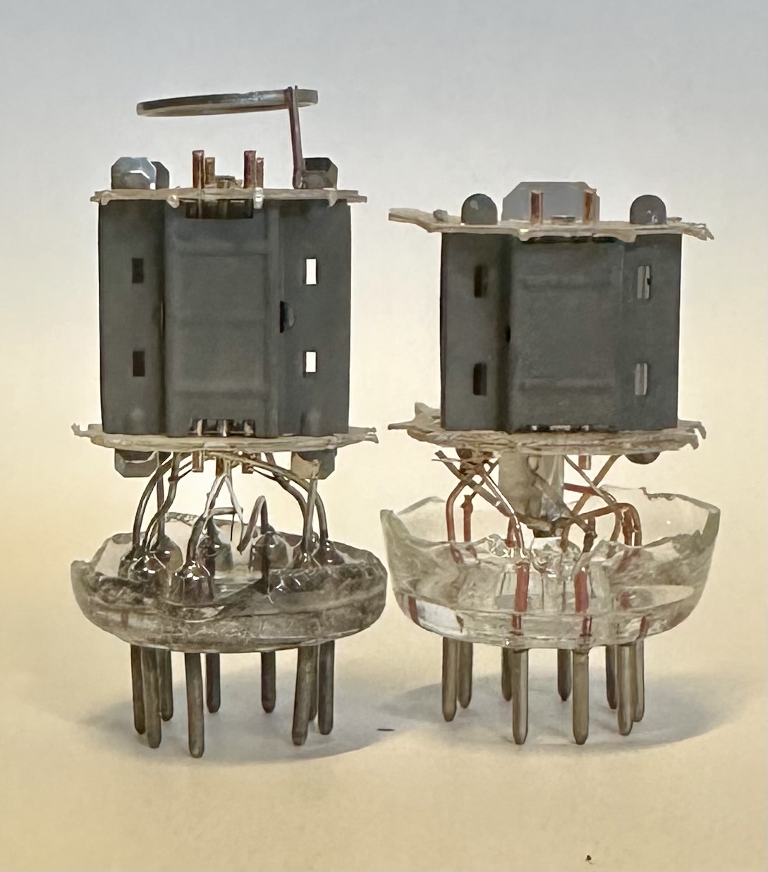
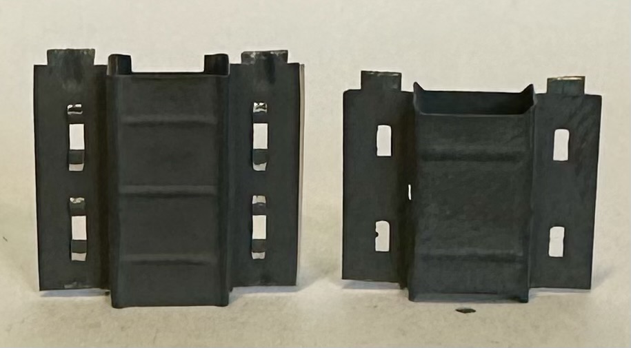
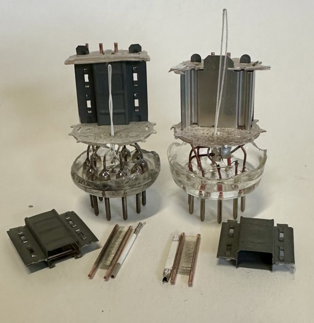
In the next series of pics we’ll get the envelopes off and take a closer look at the plates. We see two differences right off the bat. The first is the longer 0.550″ length plate of the Mullard, compared to the 0.475″ length plate of the MG. Both plates are highly magnetic, suggesting the use of a low carbon steel, or nickel/steel hybrid, with a hard aluminized coating. Both plate assemblies are crimped/stapled. The plate thickness measures 0.0045″ thick on the Mullard and 0.0055″ thick on the MG. Part of the difference here lays in the fact that the interior of the Mullard plate in uncoated, whereas as the exterior and interior of plate on the on the MG is fully coated. This suggests the Mullard plate was formed from pre coated strip material (which was very common with the classic European manufacturers) whereas the JJ plate was likely coated post forming (which was more common with the the classic American manufactures like GE).
The second big difference is the implementation of a shield between the two triodes of the JJ ECC83 MG. This is a common feature on most all of JJ’s small signal tubes, except for their long plate ECC803S and ECC802S.
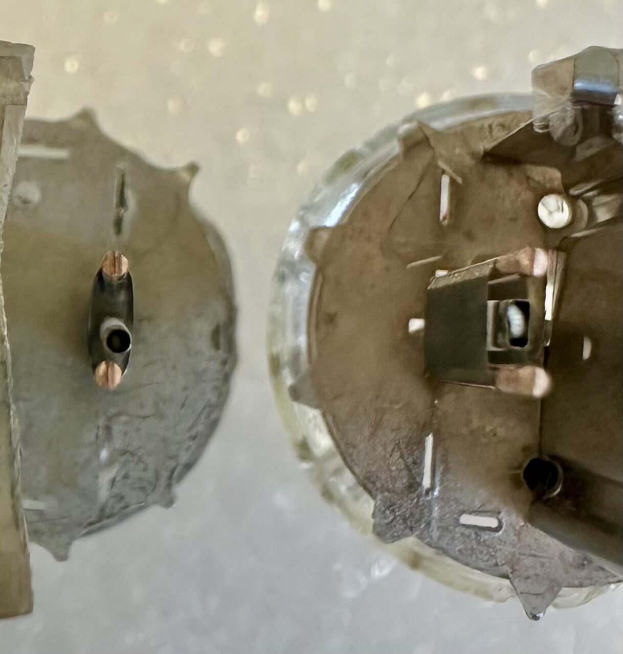
With the plates removed let’s dig into the the grids and cathodes. With the Mullard we see a finer grid pitch (around 130 turns per inch), the grid is ovalized, and wrapped around a round cathode sleeve. With the MG we see a courser grid pitch (around 110 turns per inch), the grid has been flatted, and is wrapped around a rectangular cathode sleeve. In both cases the diameter of the gird wire is around 0.001-0.0012″ thick (25-30µm)
These differences represent two different sets of compromises. In general a finer grid pitch allows the grid to be spaced farther from the cathode. This reduces contact potential, and reduces the risk of the cathode contaminating the grid over time. However, in general it’s desirable for all conducting electrodes to have a planar (Parallel Plane) relationship. If you have a round cathode, you ideally want round grids and a round plate. Or conversely, a rectangular cathode should have flatted grids and a boxed or flatted plate. This inner-electrode relationship is a major contributor in regards to linearity/distortion, and will be one of the reasons why these two tubes have different sonic signatures.
Looking through the grids we can see something these two tubes have in common, which is the cathode coating area. In both tubes the cathode coating is only applied over 0.375″ of the cathode sleeve length, and stopping well before the final turns of the grids. This means the active area of the cathode sleeve is the same for both tubes, even though the plate length of the two tubes is different. In both cases we also see best practices followed, i.e. the cathode coating stops well inside of the grid area. Like an underhung voice coil, this insures the grid has complete control over the cathode’s spaces charge. In an ideal world we would also like to see the grid extend beyond the plate structure (like a classic 45, or the current production EML 20B/AM), but that’s not possible in the confines of a small signal dual triode.
Up close we can see both cathodes have a substantial oxide coating, and the coatings are quite uniform. I can also say at this point that digging down into these tubes reveals nice details from both manufacturers. Thick treated mica wafers, hardened support rods, strong spot welds, highly uniform grid windings that have been deeply swaged into the support rods, and highly uniform cathode coatings.
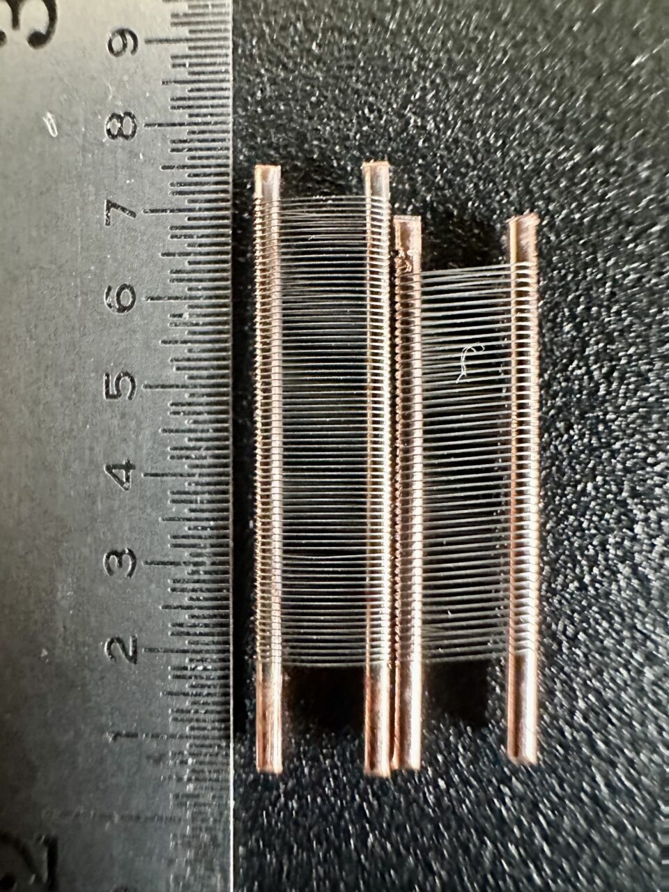
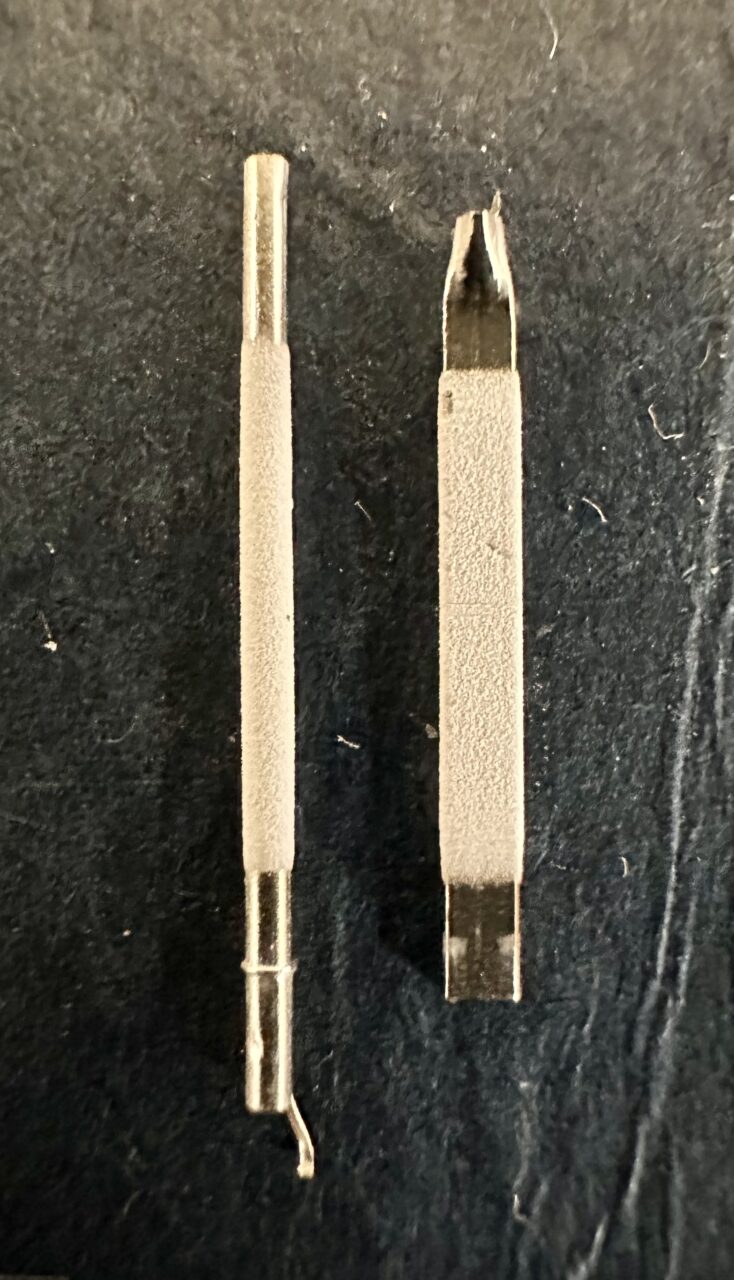
In the last pics you can see the heaters finally exposed. The JJ heater is stretched out to clearly reveal the spiral filament. Another note here, the heater insulation used in both tubes is very hard and firmly adhered to the filament. In many cathodic tubes you’ll find the heater insulation is more akin to a soft powder, which is easily scraped away. In the Mullard and MG the insulation is incredibly robust, and more akin to a ceramic coating. I can say from experience that both tubes easily handle 225VDC continuos heater-to-cathode potentials with no problems, which is a testament to the robust heater insulation.
In conclusion, we’ve found the JJ ECC83 MG is an excellent modern production option if you’re looking for a classic medium plate length 12AX7 type. Production consistency is excellent, and we see a few unique design choices that JJ has made which ultimately give the MG it’s own distinct character, while still being a well rounded and pleasant overall tube.
This article was prompted by a few of the fine folks over at the Steve Hoffman forum, who have only recently discovered the MG: https://forums.stevehoffman.tv/threads/the-most-tubey-tube-i-have-heard-deserves-its-own-thread.1247837/